
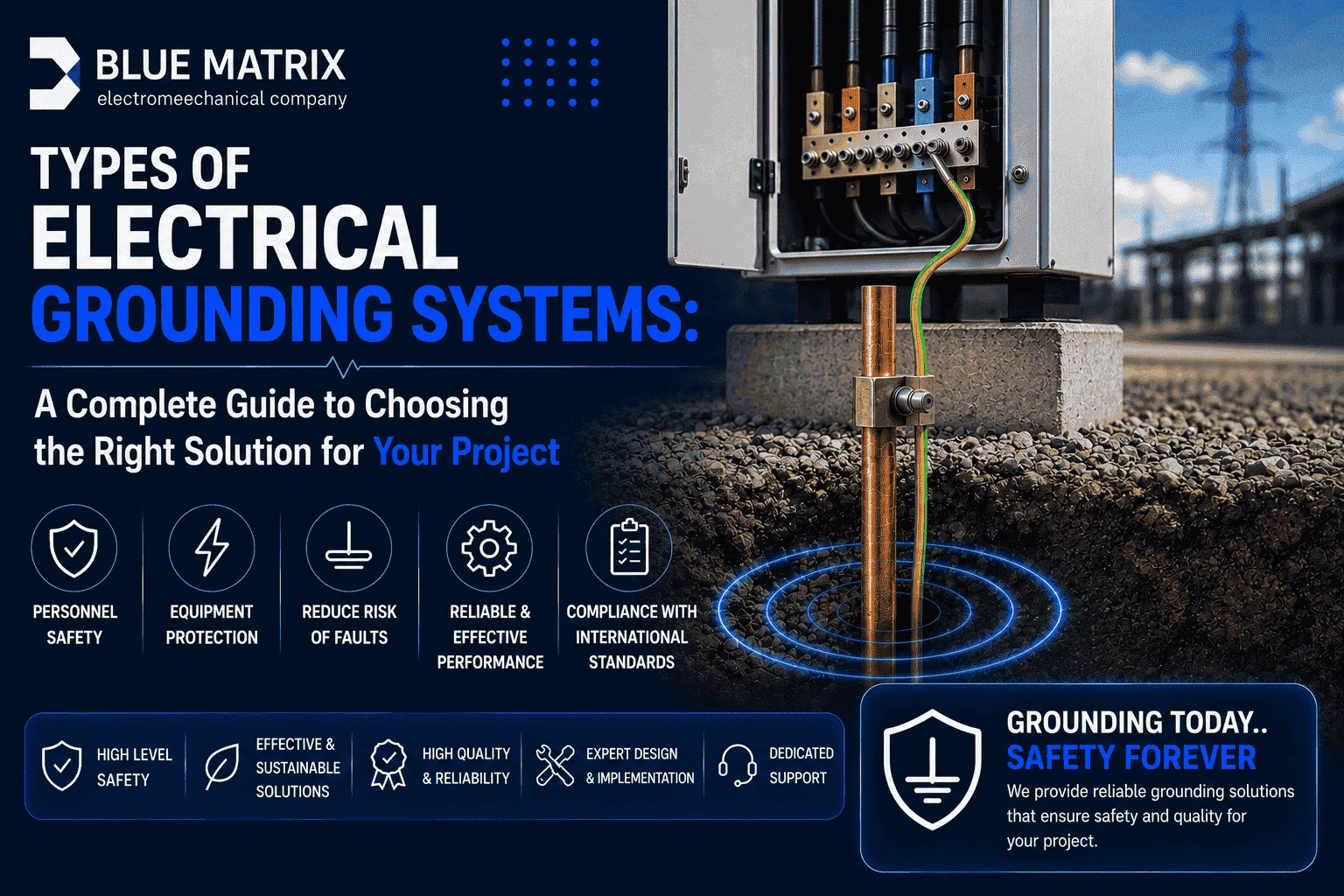
Electrical grounding is one of the most critical safety measures in any electrical installation. It provides a safe path for leakage current to flow into the earth, protecting people from electric shock, safeguarding equipment from damage, and reducing the risk of electrical fires. However, selecting the appropriate grounding system is not a random decision. It depends on the nature of the project, operational continuity requirements, soil conditions, and applicable regulatory standards.
In this guide, we explore the main types of electrical grounding systems defined by IEC 60364, with a particular focus on practical applications in the Saudi Arabian market.
What Is Electrical Grounding and Why Is It Essential?
Electrical grounding is the process of connecting the exposed conductive metal parts of electrical equipment to the earth through a dedicated protective conductor. This creates a safe alternative path for fault current whenever insulation failure occurs.
If an electrical fault energizes the metallic enclosure of a device, that enclosure becomes dangerous to anyone who touches it. When the equipment is properly grounded, the fault current flows through the grounding conductor into the earth instead of passing through a person’s body. This immediately activates protective devices such as fuses or circuit breakers, disconnecting the faulty circuit.
According to the Saudi Building Code (SBC 401), grounding systems are mandatory for residential, commercial, and industrial buildings. Ground resistance must remain within approved limits typically 1–5 ohms for standard facilities and below 1 ohm for critical installations. Failure to install an effective grounding system not only endangers lives but can also result in project rejection by regulatory authorities and expose owners to legal liability.
Types of Electrical Grounding Systems According to IEC 60364
The IEC 60364 standard classifies electrical grounding systems into three primary families. Each system is defined by how the power source is connected to earth and how exposed conductive parts are connected to earth.
The classification uses two letters:
- The first letter indicates the relationship between the power source and earth:
- T = Direct connection to earth
- I = Isolated from earth or connected through high impedance
- The second letter indicates how exposed conductive parts are connected:
- T = Connected to an independent earth electrode
- N = Connected to the earthed neutral point of the power supply
TN Grounding System
In a TN system, the transformer neutral is directly connected to earth (T), while all exposed conductive parts are connected to that grounded neutral point via a protective conductor (N).
TN systems are among the most widely used grounding methods in modern urban electrical distribution networks.
TN-S (Separate Neutral and Protective Conductors)
In the TN-S system, the protective earth conductor (PE) and the neutral conductor (N) remain completely separate from the transformer all the way to the final electrical load.
TN-S provides the highest levels of electrical safety and electromagnetic compatibility (EMC), making it the preferred choice for facilities containing:
- IT networks
- Data centers
- Sensitive electronic equipment
- Healthcare facilities
Because the protective conductor is independent of the neutral, stray currents are minimized, resulting in a more stable electrical reference and improved system reliability.
TN-C (Combined Neutral and Protective Conductor)
The TN-C system combines the protective earth and neutral functions into a single conductor known as the PEN (Protective Earth and Neutral) conductor.
Although this configuration reduces installation costs by requiring fewer conductors, it offers a lower level of safety. If the PEN conductor becomes damaged or disconnected, all connected equipment immediately loses its protective grounding.
For this reason, TN-C systems are generally prohibited in critical facilities and are primarily limited to simple industrial installations where regulations permit their use.
TN-C-S (Combined then Separate)
The TN-C-S system combines the advantages of both TN-C and TN-S.
The PEN conductor is shared from the utility transformer to the building’s main distribution point. At the main service entrance, it is separated into two independent conductors:
- Protective Earth (PE)
- Neutral (N)
This arrangement, commonly known in the United Kingdom as Protective Multiple Earthing (PME), is widely used in modern residential developments throughout Europe.
TN-C-S offers an effective balance between installation cost and electrical safety.
TT Grounding System
In the TT grounding system, the power source is directly grounded (T), while the exposed conductive parts of the electrical installation are connected to an entirely independent earth electrode (T).
Unlike TN systems, there is no metallic return path between the utility transformer and the consumer’s grounding system. Fault current returns through two separate earth electrodes and the surrounding soil.
Because this arrangement produces relatively high fault loop impedance, conventional overcurrent protective devices (MCBs) alone cannot reliably clear earth faults.
Therefore, Residual Current Devices (RCDs) are mandatory in TT installations.
Despite this additional protection requirement, TT systems provide excellent electrical isolation and reduced electrical noise, making them particularly suitable for:
- Telecommunications facilities
- Data centers requiring a clean earth reference
- Remote rural installations supplied by overhead distribution lines
- Locations where the reliability of a shared PEN conductor cannot be guaranteed
IT Grounding System
In an IT grounding system, the power source is either completely isolated from earth or connected to earth through a very high impedance (I).
As a result, when the first earth fault occurs, the fault current remains extremely smalllimited mainly by the distributed capacitance between the electrical network and earth.
This allows the electrical installation to continue operating safely without interruption after the first fault.
An Insulation Monitoring Device (IMD) continuously measures the insulation resistance of the entire electrical system and immediately alerts maintenance personnel whenever the first insulation fault is detected.
The fault must be located and repaired before a second fault occurs on another phase, as two simultaneous earth faults would effectively create a short circuit and require immediate disconnection.
The IT system is the preferred solution wherever uninterrupted electrical service is critical, including:
- Hospital operating rooms
- Intensive Care Units (ICUs)
- Underground mining facilities
- Industrial processes where unexpected shutdowns are dangerous or costly
- Offshore oil and gas platforms
- Marine electrical installations
Types of Grounding Electrodes and How to Choose the Right One
A proper understanding of electrical grounding systems is incomplete without knowing the different types of grounding electrodes used to establish a safe connection with the earth. The choice of grounding electrode depends on several factors, including soil resistivity, available installation space, achievable depth, and project budget.
Rod Earthing
Rod earthing is the most common and cost-effective grounding method. It consists of a copper or galvanized steel rod driven vertically into the ground to a depth of at least 2.5 meters. In dry or sandy soil, multiple rods can be interconnected to achieve greater depth and lower resistance. Standard rod diameters are typically 16 mm for galvanized steel and 12.5 mm for copper.
Plate Earthing
Plate earthing uses a copper plate (600 × 600 mm, 3.15 mm thick) or a galvanized steel plate (600 × 600 mm, 6.3 mm thick) buried vertically at a depth of at least 3 meters. The plate is surrounded by alternating layers of charcoal and salt to improve moisture retention and soil conductivity. This method performs particularly well in moist soil conditions.
Strip or Wire Earthing
This method utilizes a metal strip typically 25 × 4 mm copper or 25 × 1.6 mm galvanized steel buried horizontally in a trench at least 0.5 meters deep. The strip should generally be no shorter than 15 meters to achieve acceptable grounding resistance. Strip earthing is commonly used in rocky terrain, where driving deep rods is impractical.
Chemical Earthing
Chemical earthing is one of the most advanced and efficient grounding solutions for high-resistivity soils. It consists of a grounding rod surrounded by conductive natural electrolytic compounds that retain moisture and minimize corrosion. This system provides consistently low earth resistance throughout the year and requires virtually no routine maintenance or water replenishment, making it ideal for desert and arid environments.
Foundation Earthing
Foundation earthing integrates the grounding conductor directly into the building foundation during construction. It is considered one of the most reliable and durable grounding methods, although it requires early planning and coordination during the structural construction phase.
Ground Resistance: Ideal Values and How to Achieve Them
Earth resistance is the primary indicator of the quality and effectiveness of a grounding system. International standards recommend the following target values:
| Installation Type | Recommended Earth Resistance |
| Residential buildings | 1–5 Ω |
| Distribution substations | Less than 1 Ω |
| Data centers & telecommunications facilities | Less than 1 Ω |
| Hospital operating rooms | Less than 0.5 Ω |
| Oil & gas facilities | Less than 1 Ω |
Ground resistance is heavily influenced by soil resistivity, which varies according to mineral composition, moisture content, and temperature.
| Soil Type | Typical Soil Resistivity (Ω·m) |
| Wet clay | 10–100 |
| Agricultural soil | 50–200 |
| Wet sand | 100–500 |
| Dry gravel / dry sand | 500–2,000 |
| Dry rock / granite | 1,000–5,000+ |
Important Note: Soil resistivity is not constant throughout the year. Soil that measures 50 Ω·m during a wet season may exceed 300 Ω·m during dry summer months. Grounding system designs should therefore be based on the worst expected seasonal conditions.
Common Grounding Installation Mistakes to Avoid
Several installation mistakes can significantly reduce the effectiveness of an electrical grounding system:
- Using short or undersized grounding rods, which provide insufficient contact with the soil and result in high resistance.
- Failing to use corrosion-resistant materials, causing steel rods to deteriorate rapidly in moist environments.
- Poor grounding connections, as ordinary mechanical joints oxidize over time. Underground connections should ideally be made using exothermic welding.
- Neglecting periodic testing, since grounding systems require annual resistance testing and inspection after major site modifications.
- Confusing functional grounding with protective grounding. Functional grounding carries current during normal operation, whereas protective grounding operates only under fault conditions.
- Ignoring local soil characteristics, since applying the same grounding design in sandy desert soil as in fertile moist soil often leads to inadequate performance.
How to Choose the Right Electrical Grounding Contractor
Selecting the right contractor is crucial for ensuring a grounding system that performs reliably for decades.
Engineering Expertise
The contractor should have proven experience in soil resistivity analysis, grounding calculations, electrode selection, and compliance with IEC 60364 requirements.
Compliance with International Standards
Look for contractors that strictly follow:
- Saudi Building Code (SBC 401)
- IEC 60364
- NFPA 780 for lightning protection systems
High-Quality Materials
Reliable contractors use:
- Solid copper grounding rods
- Hot-dip galvanized steel electrodes
- Exothermic welded connections
- Conductive backfill materials such as Bentonite where required
Testing and Certification
Professional companies provide comprehensive ground resistance testing reports, measurement certificates, and compliance documentation after installation.
Maintenance Services
An effective contractor should also offer preventive maintenance programs, including periodic resistance testing, corrosion inspections, and grounding network maintenance.
Blue Matrix: Comprehensive Electrical Grounding Solutions
Blue Matrix provides complete electrical grounding solutions, including engineering design, material supply, installation, testing, and ongoing maintenance. Our engineering team uses advanced soil resistivity meters and earth resistance testers to develop customized grounding systems tailored to each project’s specific requirements.
Why Choose Blue Matrix?
- Customized Grounding Design based on actual on-site soil conditions rather than generic assumptions.
- Premium Materials, including solid copper rods, galvanized steel electrodes, and certified chemical grounding systems.
- Full Compliance with the Saudi Building Code and IEC 60364 standards.
- Certified Testing Reports delivered with every completed project.
- Integrated MEP Services, ensuring seamless coordination between grounding systems and the building’s electrical infrastructure.
Whether your project is residential, commercial, industrial, healthcare, or infrastructure-related, Blue Matrix delivers reliable grounding systems built to the highest standards of safety and performance.
Conclusion
Choosing the appropriate electrical grounding system requires a thorough understanding of project requirements, soil conditions, and applicable safety standards. No single grounding system is suitable for every application; each offers distinct advantages depending on the operating environment.
Investing in a properly designed and professionally installed grounding system helps protect human life, electrical equipment, and operational continuity. To learn more about our electrical engineering and grounding solutions, contact the Blue Matrix engineering team.
Frequently Asked Questions (FAQ)
What is the difference between grounding and bonding?
Grounding connects electrical equipment to the earth, while bonding electrically connects exposed conductive parts together to maintain the same electrical potential.
Which grounding system is better: TN-S or TT?
TN-S provides superior safety and electromagnetic compatibility, making it ideal for modern buildings and sensitive facilities. TT is generally preferred in rural areas or locations where the integrity of the PEN conductor cannot be guaranteed.
How much does a residential grounding system cost?
Costs vary depending on the building size, soil conditions, and the number of grounding electrodes required. A detailed quotation can be provided following a site assessment.
Can a grounding system be installed after construction is complete?
Yes. However, retrofitting is generally more difficult and expensive than installing the grounding system during the construction phase.
How long does a grounding system last?
Conventional grounding systems require periodic maintenance every 6–12 months, while properly installed chemical grounding systems can operate effectively for many years with minimal maintenance.
How is ground resistance measured?
Ground resistance is measured using an Earth Resistance Tester (Megger), which calculates resistance between the grounding electrode and true earth using auxiliary test probes.
Does grounding protect against lightning strikes?
Protective grounding safeguards against insulation faults, while lightning protection requires a dedicated Lightning Protection System (LPS) consisting of air terminals, down conductors, and grounding electrodes.
What happens if a building has no grounding system?
Failure to comply with Saudi Building Code grounding requirements may result in project rejection, regulatory penalties, and legal liability if accidents occur.
Can water pipes be used as grounding electrodes?
Although this practice was common in the past, modern electrical standards prohibit relying solely on water pipes because many have been replaced with plastic piping, which provides no electrical continuity.
What are the signs of a poor grounding system?
Common warning signs include:
- Unexplained increases in electricity consumption
- Sparking when touching metal equipment
- Overheating electrical conductors
- Frequent circuit breaker trips or power interruptions
Related Articles
- Best Types of Fire Pumps: A Complete Guide to Choosing
- Difference Between FM200 and CO2 | A Complete Fire Suppression Guide
- Types of Air Conditioning Systems | Best Cooling Solutions for Your Project
- Professional Electrical Contractor | Electrical Installation & Maintenance